1. Product Overview
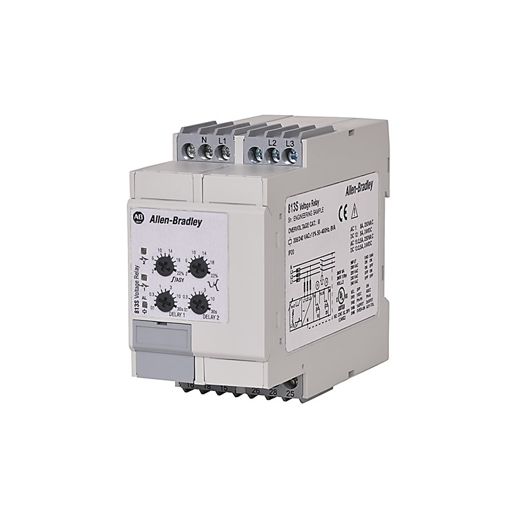
• Model: 813S-V3-480V
• Type: Three-phase voltage monitoring relay (utilizing TRMS technology)
• Core Functions:
Monitors overvoltage, undervoltage, phase sequence errors, phase loss, voltage asymmetry, and tolerance in three-phase systems.
Features a self-powered design (no external power supply required), suitable for industrial motor protection systems.
• Applicable Scenarios: 440–480V AC three-phase balanced systems with a frequency range of 50–400 Hz.
• Key Features:
Dual Form C output contacts (normally closed).
Adjustable delay times, latch, and inhibit functions.
LED status indicators (red flashing indicates an abnormality).
2. Core Specifications
Input Specifications
Parameter Value
Input Terminals Terminals 1, L2, L3, N
Power Supply Range 440–480V AC
Power Supply Method Self-powered
Frequency Range 50–400 Hz
Monitoring Range Settings
Parameter Value
Upper Level 2–22% of nominal voltage (adjustable)
Lower Level -22% to +2% of nominal voltage (adjustable)
Asymmetry 2–22% of nominal voltage (adjustable)
Tolerance 2–22% of nominal voltage (adjustable)
Hysteresis
Setting Point Value
2–5% 1%
5–22% 2%
Output Specifications
Parameter Value
Contact Type (2) Form C, Normally Energized (double-pole double-throw, normally closed)
Rated Insulation Voltage 250V AC
Rated Operating Power 13 VA @ Δ 400V AC, 50 Hz
General Specifications
Parameter Value
Power ON Delay 1 s ± 0.5 s or 6 s ± 0.5 s (optional)
Degree of Protection (IP) IP 20
Pollution Degree 3
Dimensions (Width × Height × Depth) 45 × 80 × 99.5 mm
Screw Terminal Torque Maximum 0.5 N-m
Certifications and Compliance
• Standards: EN 60664, EN 60038, UL 508
• Certifications: dULus listed (File E14840, Guide NKCR, NKCF7)
3. Functional Features and Wiring Instructions
Core Functional Logic
• Response to Voltage Abnormalities:
If any inter-phase/phase-to-neutral voltage exceeds the limit → Red LED flashes → Output relay releases after a delay.
In case of phase sequence errors or phase loss → All output relays release immediately.
• Special Functions:
Latch: Maintains the triggered state of the relay until manually reset.
Inhibit: Prevents false triggering (e.g., during motor startup).


